High-dynamic-range and low-power M-MIMO Communications. The massive multiple-input multiple-output architecture (M-MIMO) is a communication system that utilizes a large number of antennas and the base station, serving a large number of users. While M-MIMO offers substantial potential for spectral efficiency gains, it faces considerable practical challenges. Among the limitations are the power consumption and receiver saturation, which are particularly critical in M-MIMO since each antenna has a corresponding radio frequency (RF) chain.
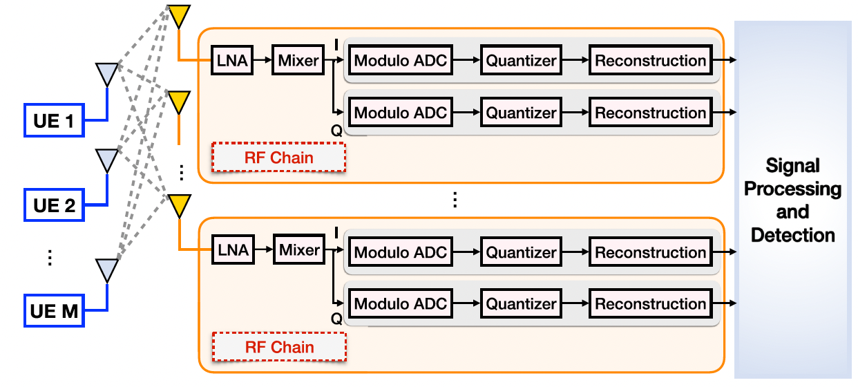
\(\lambda\)-MIMO is a new approach for holistically addressing the high power consumption and receiver saturation problems in M-MIMO architectures. Compared to de-coupled approaches, the overall performance can be optimized, as balancing trade-offs can be avoided. The uplink system architecture is constructed by replacing the ADC in each RG chain by the M-ADC.
Theoretical analysis and hardware experiments indicate that the proposed \(\lambda\)-MIMO architecture achieves better energy efficiency compared to the conventional M-MIMO architecture. The reconstruction, detection and sum-rate performance are also improved.
System Model. At the transmitter side, the Narrowband Single-Carrier Signal Model (NBSC) and the wideband MIMO–OFDM were studied.
At the receiver side, the received signal at the \(n^{\mathsf{th}}\) antenna, denoted by \(z_{n}(t)\)
is amplified and de-modulated to the baseband. The quadrature and in-phase signal are then lowpass filtered, and sampled by the M-ADC.
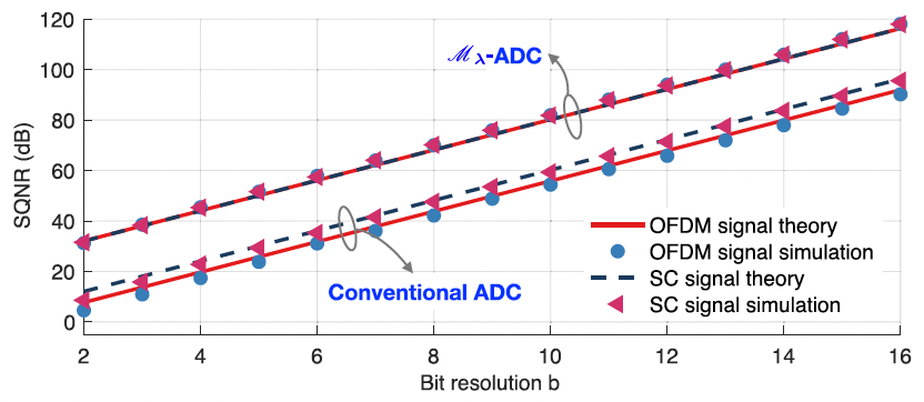
The M-ADC achieves lower quantization noise (more information: Sampling Resolution), and the impact on the performance of communication is shown by analyzing the analysis of the SQNR and achievable sum-rate for a maximum ratio combining (MRC), and zero forcing (ZF) combiners.
SQNR
The baseband sampled single-carrier signal is subject to uniform distribution \(r[k] \sim U(0,1)\).
The SQNR for a conventional ADC is: \(\text{SQNR}_{\text{unif}} = 10 \log_{10} \frac{\sigma^2_{r,\text{unif}}}{\sigma^2_{q,\text{unif}}} = 6.02 b \, (\text{dB})\).
The modulo folded samples follow a uniform distribution \(\mathscr{M}_{\lambda}(r(t))\vert_{t=kT} \sim U(0, \zeta^{2})\).
Consequentially, the quantization error is lowered by: \(\sigma^2_{q,\lambda} = \zeta^2 \sigma^2_{q,\text{unif}}\), and the SQNR becomes:
Notably, the M-ADC gives an \(20 \log_{10}(1/\zeta)\) enhancement on the SQNR.
The OFDM signal is commonly assumed to be a centered, wide-sense stationary, ergodic Gaussian process \(r[k] \sim \mathcal{N}(0,1)\).
The SQNR for a conventional ADC is: \(\text{SQNR}_{\text{Gau}} = 10 \log_{10} \frac{\sigma^2_{r,\text{Gau}}}{\sigma^2_{q,\text{Gau},(m)}}\approx 6.02 b - 4.35\).
The modulo folded samples follow a wrapped distribution, which was empirically found to be uniform \(\mathscr{M}_{\lambda}(r(t))\vert_{t=kT} \sim U(0, \zeta^{2})\) for \(\lambda\) being a fraction of \(\sigma^{2}\).
The SQNR is,
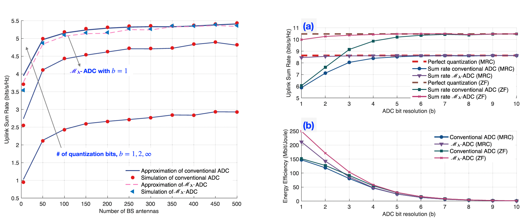
where \(I_{\text{ZF}}\) is the expectation of the noise-plus-interference term. Here, \(\delta < 1\) is the attenuation coefficient.
The following figure present the comparison of the sum-rate for conventional and M-ADC on simulated data. As observed, by setting \(b\) as low as \(1\) or \(2\) with M-ADC the up-link sum-rate approaches that of \(b=\infty\) for conventional ADC.