Diary of May 2002 7-15
May 7, 2002I couldn't solve the alignment problem: the diodes are too tight, and if they would not be tight, every pull on the signal wires would de-align them. Solutions: Wrapping a cord (0.025 elastic wire) twice around the front part of the diode. Disadvantage: too difficult to align. Pull of wires would misalign the assembly.
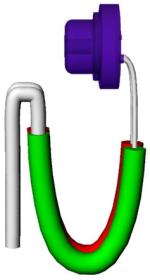
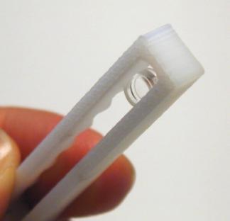
Finally, I designed a solution that uses just two parallel, isolated, soft wires that are soldered to the laser's pins, and glued each with two holes to the 3D printed holder, with a U shaped ending (Figure 104).
Therefore, one inner side of the holder had to be made thinner, so that the wires (the U part) do not get in the way of the laser path. The connections (GND and signal) would be soldered on the other side of the U, which deflects all forces away from the wires that hold the diodes.
During the day, I could not print another diode holder because there was a 16-hour job on the 3D printer that started at 5pm. So I decided to experiment with an earlier version of the holder, cutting away the back of the holder.
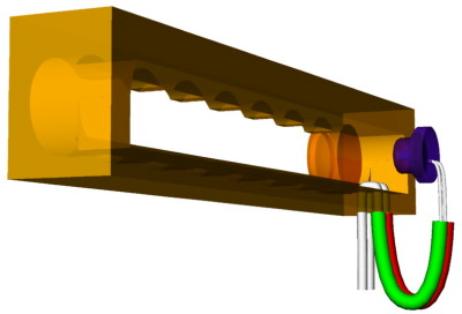
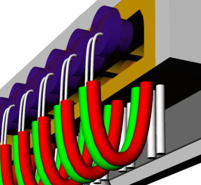
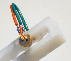
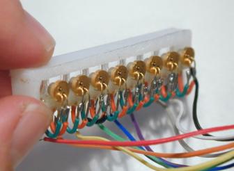
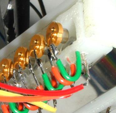
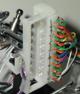
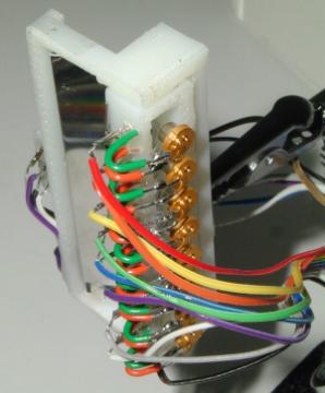
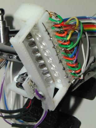
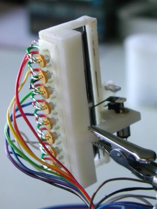
May 8, 2002I finally 3D printed several versions of the diode holder (Figure 105).
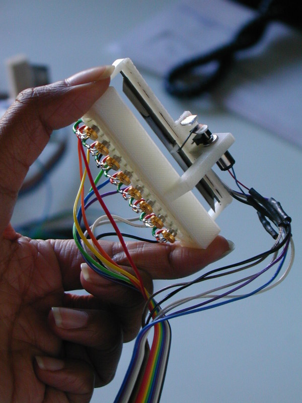
I assembled one, by drilling 32 holes manually (four for each laser: a pair for ground, and a pair for current), and inserting isolated wire from jumper wire kit, which was a pain. Epoxy glued the wires in. Connected all the GND pins with one stiff piece of wire. Aligned the laser diodes (was possible, but still took some time): the alignment is on an acceptable level now.
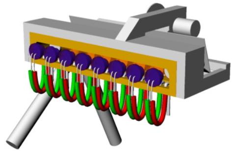
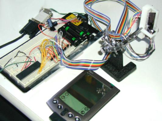
In the following, a few pictures of the completed TinyProjector prototype 9.
Then I wrote all software for receiving serial code, and writing single characters (A-Z, !) (Figure 109)
Later, I added some preset text lines that are triggered by sending single digits from 2-9 over the serial port to the PIC.
Then I connected the TinyProjector prototype 9 to Natalia's Palm 5, and it worked well with Pterminal and Graffiti (Figure 110).
However, there was still a problem: the sensor seems to fluctuate, generating horizontal jitter in the projection. Either it is mechanical imperfections of the servo arm (tried to make it better, but was not successful), or to much stray light (built a cardboard casing around the IR and diode, but did not seem to make a difference.)
Stayed up all night to make it work! Here are the problems that came up:
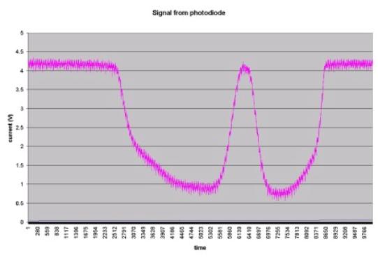
May 14, 2002I connected the photodiode to the oscilloscope: it indeed showed a double triggering. The peaks are about 10ms apart. Furthermore, Gerardo says that the levels are very low: 1V is the max (which is strange, because I think I measured it earlier, and it gave 4.5V)
May 15, 2002With Gerardo's help, I measured the output of the photodiode (again). On a voltmeter, it is between 1V and 4.3V. Then, we measured on an oscilloscope, and it looked similar. (The measurements yesterday were not correct; there must have been some problems with the settings.) The signal is generally high at 4.3V, and drops to approx. 1V when the servo arm passes. Actually, it has two lows, separated with a high spike. First we thought that this is causing the jittering: sometimes the PIC detects the first low, sometimes the second. However, that is not the case, because when the PIC detects the first low, it waits 15ms, and then starts with the blinking sequence that in itself lasts 9.6ms. Therefore, the PIC detects a low, and then ignores the photodiode signal for 25ms, and only then looks for a low again. At that point, the signal is high again for sure.
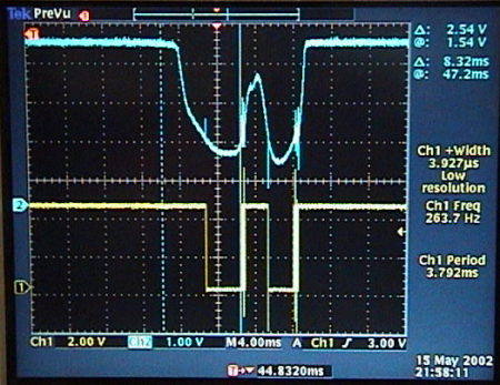
In order to solve the jittering problem, we inserted a Schmitt trigger (with buffer) to straighten out the signal (see screenshots, Figure 112). Although the signal looks very clean now (no slopes anymore), both the signal in the oscillator and the projection still jitter. These two might actually not be because of the same reason.
The oscillator says that the signal frequency that comes from the photodiode is between 120 and 145Hz. However, it doesn't really matter that this frequency is not constant, if the motor (rotation speed) is the reason for the jittering of the oscillator signal. Such a variation would just translate in a variable refresh rate, which is not relevant.
If the motor is the reason for the jitter in the oscilloscope signal, then it is the connection between motor and mirror that is reason for the jitter in the projection. Whenever the photodiode triggers the laser sequence, the mirror has to be at the same place. That does not seem to be the case: it's probably the connection (hole) between the servo arm and the pushrod that wears out more and more. One solution would be to glue in a ball bearing instead of a plain hole, another one could be to use thicker material or harder material, like aluminum as a servo arm.
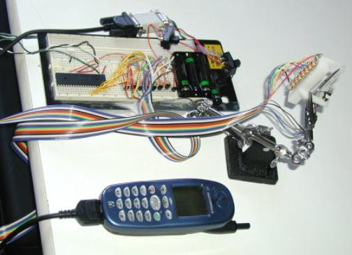
Natalia gave me an iDen phone with a little Java application that sends characters to the serial port (Figure 113).
Send me some comments! Copyright © 1997-2004 by Stefan Marti and MIT Media Lab. All rights reserved | |||||||||||||||||||||||||||||||||||||