Diary of April 2002 22-30
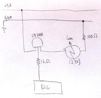
April 22, 2002I met with Vadim about a voltage regulator for the laser diode and the motor. For the laser diode, I just need a resistor; Vadim estimates between 10 and 100 Ohm (Figure 67).
To find out the right resistance, he suggests using a potentiometer and then start from its highest resistance to low until the diode lights up, and then measure the resistance of the potentiometer.
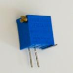
As a potentiometer, I used a Bourns 3299-102 (1kOhm) (http://www.bourns.com/pdf/3299.pdf) (Figure 68)
My first Lumex laser diode seemed to be doing fine with 60 Ohm, but then died suddenly. For the next diode, I stopped at 100 Ohm, and it seems bright enough.
I measured the focal length again: it is pretty much 5mm.
For the motor, I will probably need a Maxim 825: http://pdfserv.maxim-ic.com/arpdf/MAX823-MAX825.pdf [It turned out later that I do not need any specific op amp for the motor.]
I set up the PIC 16F877 on a new breadboard
I unsoldered IR LED/photodiode from the MS Trekker mouse (with the solder "sucker" device, thanks Natalia (nmarmas@media.mit.edu), and set up LED and IR LED/photodiode on the breadboard.
I killed first IR LED from the computer mouse by not using a resistor. Looked for replacement: is it this one? http://www.fairchildsemi.com/ds/QE/QEE213.pdf
Installed a 300 Ohm resistor for the IR diode, a 100 Ohm resistor for the test LED, and will use another 100 Ohm resistor for the laser diode.
April 23, 2002I debugged the 16F877 hardware:
April 24, 2002I made the photodiode and IR LED work. Software and hardware were OK: the photodiode gives about 5.1V when the LED shines, and when shaded less than 1.5V, and that’s where the PIC switches.
The problem was only that my desk lamp actually emits IR light, so it was not possible to shade the photodiode at all! Further, normal white paper or foam or Post It’s seem to be translucent for IR light: even white plastic gears do not shade enough. It has to be either metal (I tried the stainless steel strips), or black colored tape (on a business card).
The IR seems to be very strong (or the photodiode very sensitive), so the hole that lets light through can be very small. Currently, I use a slit of about half a millimeter width in the business card covered with black tape.
I could not find out where the photodiode is most sensitive (there are actually two diodes in this element): the whole surface of the photodiode has to be covered so that it goes below 1.5V (which is when the PIC decides it is LOW).
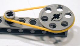
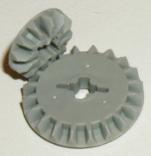
April 26, 2002For the gearbox (V-belt, pulleys), I found LEGO Technic gear that might help: pulleys, rubber belts (probably better than O-rings!), axles, gears, etc. (Figure 69)
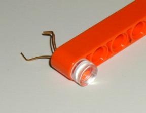
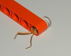
Two different LEGO bars work almost perfectly: in one of them (Figure 70), the diode can slide slightly horizontally, which would allow for alignment. However, the lens would be a little too close to the diode, so in order to focus it, it had to be raised by a fraction of a millimeter (with very thin cardboard). That's not very precise.
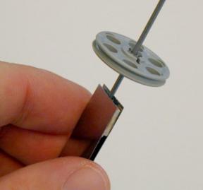
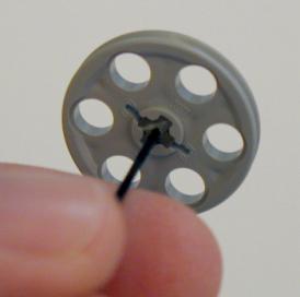
In order to fit gears and pulleys on my 2/32-inch and 1mm axle, I drilled holes in LEGO axles (Figure 71)—manually, without drill! I still need a 1mm drill bit (did it with the 1/32 bit I got from Brygg: also not long enough): the holes are good, but not completely centered. I should do that with a mounted drill. The hand drills I saw cannot take 1mm drill bits.
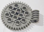
I did many tests with different kinds of gears and 1.5 - 4.5V and the medium 10mm Ballooncraft motor (Mabuchi MV2A, http://www.toytx.com/1015vmic.html): normal gears, bevel gears, and pulleys/rubber belt. The last one is the best because it is the most quiet, and the wheels do not have to be aligned perfectly (and it is difficult to align them perfectly!) With 1.5V, it runs very quietly. However, the distance has to be exactly right: if the motor is too far, the tension is too big; if it is too close, the belt is too loose and "wobbles". That could become tricky.
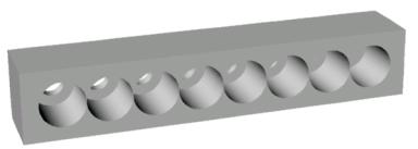
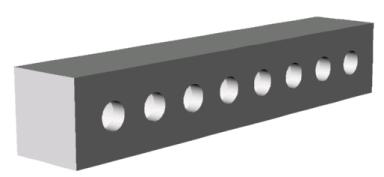
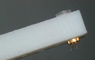
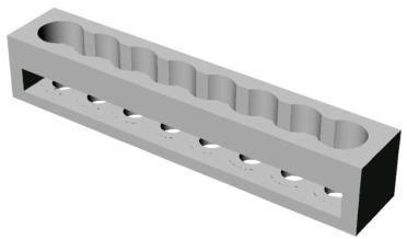
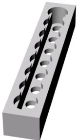
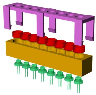
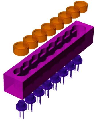
Since the Lego holders were not exact enough, I designed a new casing, just for the diodes and lenses (casing1.3dm) (Figure 72). This is going to be TinyProjector prototype 5.
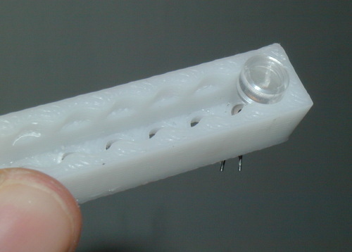
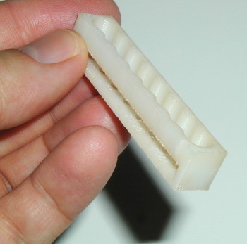
I 3D printed this design, which took only 27 minutes, since there was very little support material necessary (Figure 73).
The holes for the diodes are perfect (3.7mm diameter), but the holes for the lenses are a bit too tight (7mm). Also, it will be difficult to put them in there because in order to press one in, the other basically becomes loose, because the upper part of the holder is a bit flexible. Being flexible is good, but not for all lenses at the same time.
April 28, 2002I made a new mirror holding assembly (Rhino, and then 3D printed), three versions:
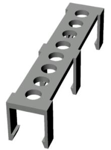
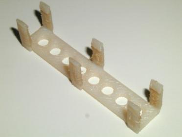
Version 1 (Figure 74, Figure 75): Lens holes 7.00mm diameter, slit on the side: good because the lenses can be snapped in. Not so good because whenever one lens is moved, all the lenses are unlocked, move, and even fall out) (casing1.3dm)
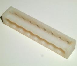
Version 2 (Figure 76, Figure 77): Holes 7.20mm, 2mm deep, no slit. Lenses still too loose and keep falling out, so I designed and printed the lid, which should snap on top of the casing, holding down the lenses. Lid is not precise enough, though (casing2.3dm and casing_lid.3dm).
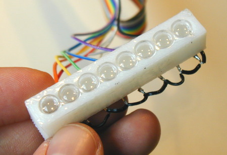
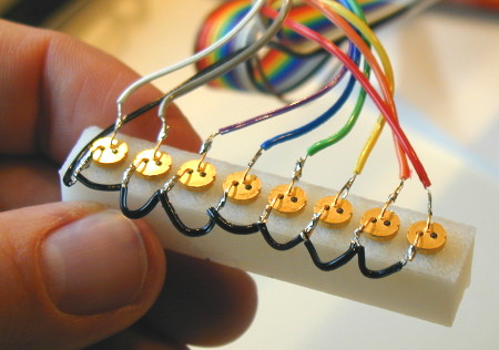
Version 3 (see Figure 78, Figure 79, Figure 80): Lens holes 7.10mm diameter, 3mm deep, and no slit. Lenses fit nicely now, and are even with the casing outside. No need for a lid, a simple clear transparent Scotch tape is good enough. Focal length seems to be optimal (5mm), the laser diode has to be pulled back only a fraction of a millimeter to get it in focus (casing3.3dm).
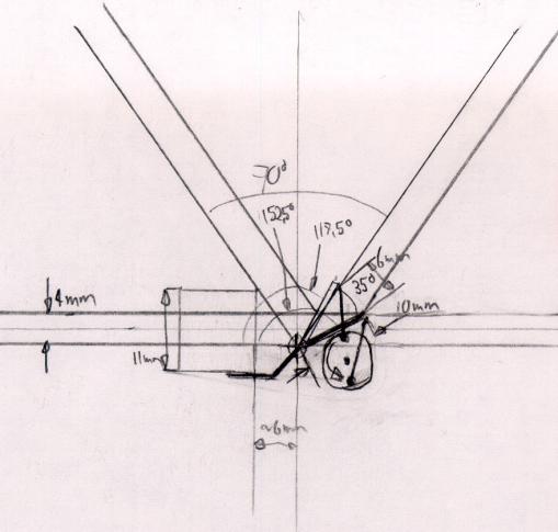
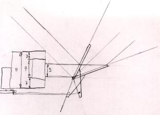
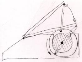
April 29, 2002I made drawings and calculations of left-right sweeping mirror assembly for the new casing: a rotating disc is mounted directly on a small pager motor (Figure 81, Figure 82).
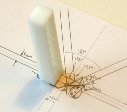
I assembled a holder prototype (see also Figure 87), with a 13mm-wide mirror: the small pager motor can turn it only with 3V and 4.5V (1.5V not strong enough), and it is rather loud. Mechanically, it is much simpler than the rotating mirror, so perhaps I keep this assembly in case I can't make the other one.
April 30, 2002I tried to buy 1mm and 1.5mm rods from MIT Central Machine and Pearl Arts and Craft store. None of them had, but I bought a series of rods and tubes, both steel and brass. http://web.mit.edu/cmshop/mshop.html
Eventually, I found a coated steel wire that has a diameter of 1.2mm (with coat), and about 0.9mm (without coat). The plastic coat is very useful to link the 1mm axle of the small pager motor. If a scotch tape is wrapped around the uncoated wire, the diameter is pretty much 1mm!
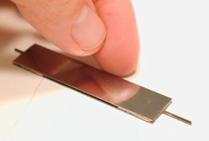
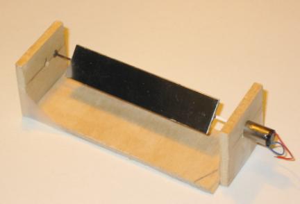
I made a double-sided mirror with the 0.9mm rod, two mirrors (13mmx60mm), and 5-minute epoxy resin (Figure 84).
I made a crude assembly out of three hard wood pieces (Figure 85): one for the ball bearings (bore 1mm, outer diameter 3mm), with a 2.45mm hole, the other for the small pager motor, with a 6mm hole. The holes were drilled in the machine shop, on the big vertical drill. This was the first version of TinyProjector prototype 6.
The mirror assembly works well: it is noisy at 3V, but very quiet at 1.5V. Looks like it could work that way!
Send me some comments! Copyright © 1997-2004 by Stefan Marti and MIT Media Lab. All rights reserved | ||||||||||||||||||||||||||||||||||||||||||||||||||||||||