Diary of March 2002 22-31
March 22, 20023D printed TinyProjector prototype 3 on our Stratasys FDM 2000 with the following settings:
Material: ABS P400 Alternate Material: P400-SR Soluble Heads: both T16 Slice size: 0.014
March 25, 2002I cleaned the 3D printed parts in ultrasonic bath.
Then I drilled holes in the turning parts: although they were part of the 3D printed model, the holes did not come out properly and had to be re-drilled.
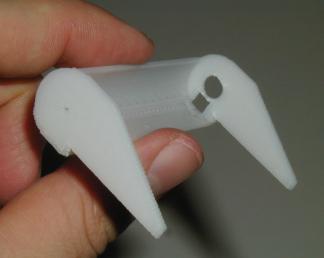
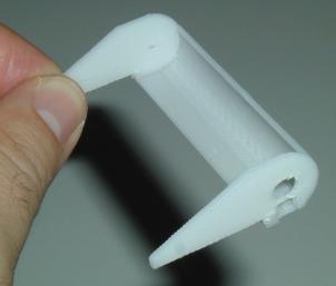
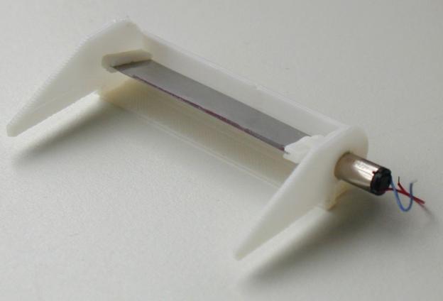
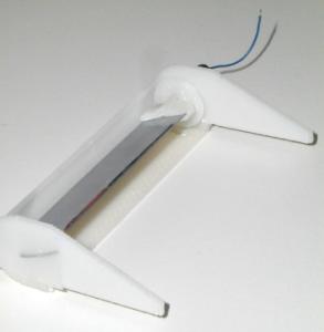
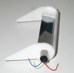
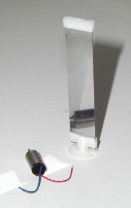
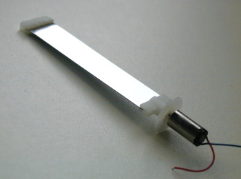
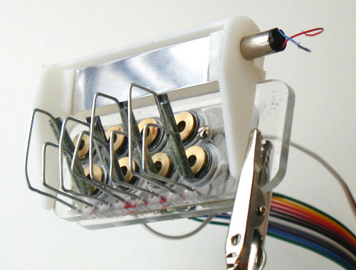
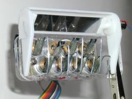
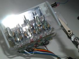
The following pictures (Figure 49) show the 3D printed parts, fully assembled with the pager motor (Mabuchi J20WA), and the stainless steel mirror. The axle on the opposite side of the motor is a simple steel rod. For size comparison: overall size of the assembly is 68mm, and the motor has a diameter of 6mm.
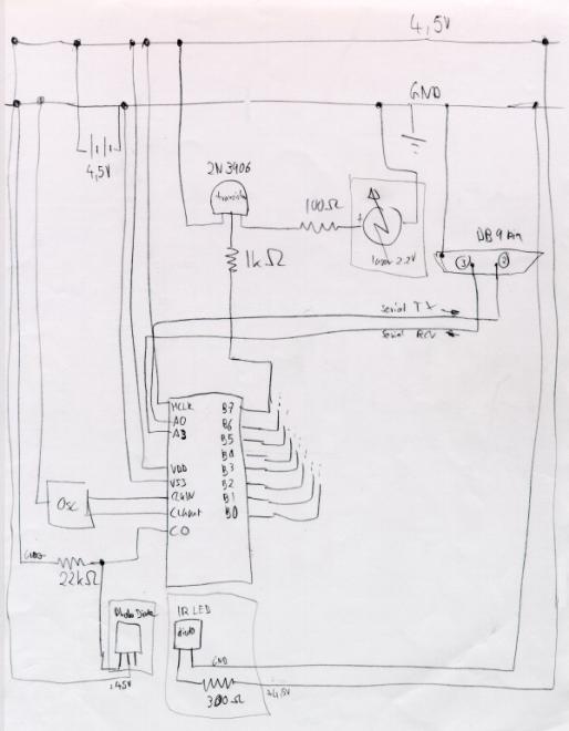
Later I sketched out the schematics for the current projector, determining which pins are for serial, what are the values of the resistors, which pins on the PIC are free, etc (Figure 51).
March 26, 2002I 3D printed the mirror holders again, with smaller diameter and bigger holes. They fit better now, but the mirror has still too high friction, or the motor is too weak to turn it in direct drive.
Either I have to find a mechanically better solution (e.g., more precise mirror holders: 3D print again, and drill the holes with the fixed drill), or accept that it is not turning easy enough and just use a bigger motor (which can't have a bigger diameter, because of the photo diode).
A third solution would be to use gears (snake gear, or rubber band transmission), and then the motor would probably have enough torque.
A fourth solution is to stiffen the mirror with an axle. (This will be the option that I will follow up on, see Figure 84.)
I also made another PIC-to-serial cable, to connect the breadboard to the laptop (different serial pin out as for the Palm)
I burnt another PIC chip (16F84A) to test the serial I/O: even with the INVERT, it doesn't accept serial input. I really have to contact Vadim about that.
March 27, 2002Vadim helped me debug serial input/output for two hours; he fixed many problems (e.g., set_tris was wrong), but he couldn't make it work (there seem to be some dependencies between PIC pin A0 and A1, during the '#use rs232' statement). Later, I got it working with pins A0 and A3.
Furthermore, SEND didn't work when and LED was connected. (RECEIVE always worked, and showed incoming activity nicely.)
The resistors in the path of SEND and RECEIVE as well as MCLR are not necessary, they were all removed. That makes the circuit simpler.
Debugged new code (new_choi.c), and run into memory limitations (not enough space for all variables): I will have to use a PIC with more memory, perhaps the 16F877?
At least one laser diode is broken (the top most) and has to be replaced; a second one has temporary outs and is flaky. I will soon run out of laser diodes, so I have to order more on eBay.
I took many pictures of the 3D printed model of TinyProjector prototype 3 and mirror (Figure 4; see also Figure 49 and Figure 50).
March 28, 2002I started using at 16F877 PIC: I wrote software that has patterns for all characters, digits, and many special characters. However, this program is too big even for the 16F877. Vadim suggests using the internal EEPROM memory for the constants. The program with the characters only fits into the chip, though.
I asked Chris for more laser diodes. I also emailed Lumex for sample laser diodes (5.6mm, 20 pieces, usually $5.37).
March 29, 2002I figured out how to program to the internal EEPROM of the 16F877.
I tested several electronics schematics design programs; best is probably still Protel.
I ordered 30 cheap key chain laser pointers.
I did some Web searching about the new Honeywell diodes http://content.honeywell.com/vcsel/pdf/sv3644-001.pdf and why they are different from, e.g., Lumex ones http://www.lumex.com/pls/lumex/subproduct_galary?iproduct_id=1000901
Main difference is the beam divergence: Lumex has 9 (vertical) to 35 (horizontal) degrees, similar to my key chain lasers. The new Honeywell VCSEL have more like 10-15 degrees and is oval, which means the lens can be smaller and closer. But they are also less bright: 1.5mW vs. 5mW (Figure 53).
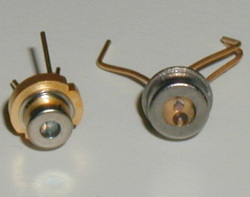
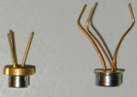
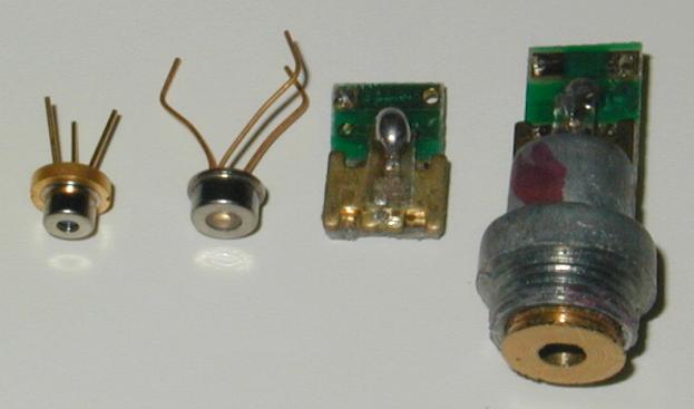
With these numbers in mind, I was starting to wonder about the beam angle (without lens) of my current old laser diodes, the “flat” ones, salvaged from the laser pointers (see Figure 54):
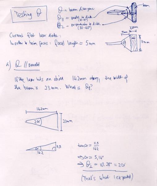
Measurements of my old (flat) laser diodes show that if its beam hits a surface 142mm away, the width is 23mm. This results in a beam angle (Theta parallel, θ║) of about 10 degrees (Figure 55):
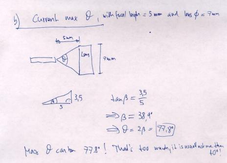
Then I calculated the maximum angle of the laser diode beam if a 7mm diameter lens is put 5mm away (which is the case in the key chain laser pointers): it is about 78 degrees (Figure 56):
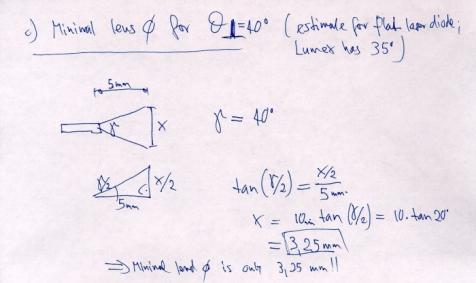
However, since I was thinking about using the small Lumex diodes that have a maximum theta of 35 degrees, I realized that the lenses could actually be much smaller in diameter than the 7mm-diameter lenses that I am using right now.
This is important
since the lens diameter dictates the overall length of a laser array. The
smaller the lenses, the smaller the projector! It turns out that a lens for a
diode with a maximum theta of 40 degrees needs only a diameter of 3.25mm! (Figure 57) This is very good news.
March 30, 2002TinyProjector specifications for the next prototype, and proposed solutions:
Ball bearings: http://db.rmb-group.com/b/rmb.taf?_function=detail&_UserReference=E33AB9720CA891723CA5FC00
More design ideas:
Send me some comments! Copyright © 1997-2004 by Stefan Marti and MIT Media Lab. All rights reserved | ||||||||||||||||||||||||||||||||||||||||||||||||||