Diary of March 2002 1-21
March 7, 2002After a six-month break during which I had to attend other business (my qualifying exam, basically), we decided to continue the work on the TinyProjector.
I had a 3-hour brainstorming with Wilfrido Sierra (wsierra@media.mit.edu) and Jonathan Brill (jonathanbrill@hotmail.com) about the design of a new projector.
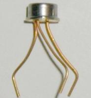
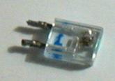
Will showed me his laser diodes (6$, from Honeywell; not (yet) publicly available, he got them via Mike Bove, http://content.honeywell.com/vcsel/pdf/sv3644-001.pdf, see Figure 37), and his laser array (with the custom-molded lens array).
He was interested in the lenses I have, scavenged from the cheap key chain laser pointer diodes, so I gave him three of mine. My diodes (without casing and lenses) break very fast and seem very sensitive to vibration; his seem to be more rugged.
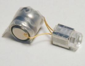
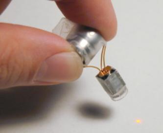
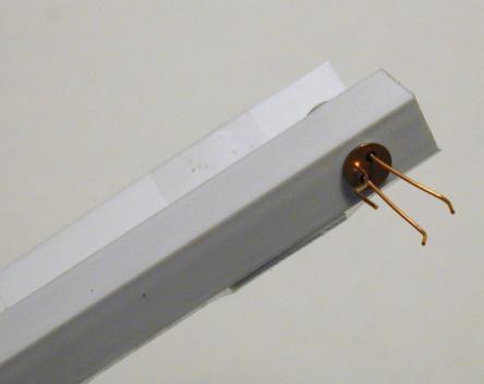
I also made a distance holder from a square aluminum tube for a single Honeywell VCSEL diode and an old lens (about 8mm distance). The lens is not symmetric, though; the round part has to look away from the diode. The voltage is 2.3 -2.7V, and it seems to be resistant to under and over voltage (it just doesn't work if not the right voltage). Used two old LR44 button batteries (total about 2.7V) to power it. Brightness is much less than old laser diode, but in a much smaller package (Figure 38).
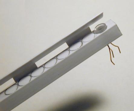
I also made a mockup of a plastic square tube (diameter has almost the right distance to hold the lens in right distance from the diode) that could hold all 8 diodes/lenses (replacing the single aluminum square tube) (Figure 39).
I also did a Web search for PIC controllers that have bigger memory than the 16F84: looks like the 16F87 and 16F88 have four times the memory, and seems to be pin compatible with the 16F8's. However, unfortunately, they have status "future product"… http://www.microchip.com/download/lit/pline/picmicro/families/16f8x/39568b.pdf
I found some example code for the 16F87X, which uses the CCS and has arrays in it: http://www.phanderson.com/icd/PIC16F87X_tutorial_sample.pdf
Then I wrote some PIC code that is more systematic than the old one, trying to optimize the algorithm of creating the patterns (Figure 40):
March 11, 2002I had a meeting with Chris about the TinyProjector.
I updated him on new diodes from Mike: could make a simpler, more robust, and smaller prototype.
We should focus on interaction modes: RSVP, scrolling, etc. Find good applications (or scenarios).
It will be a closed project, done after I have made it work.
He asks: Will it be loud? Probably.
In order to make it quieter, I was thinking about using a magnetic actuator to move the mirror, like a BIRD, CETO, or a MiniMag actuator:
I asked Mike Bove (vmb@media.mit.edu) about more diodes at: http://content.honeywell.com/vcsel/pdf/sv3644-001.pdf
He says, Honeywell does not have a lot of them, but if he gets more, and Will doesn't need them, I can have them.
I should ask Will what he plans to show for the Spring open houses, so that I don’t do something that he shows also.
March 14, 2002I simplified the servo idea drastically: instead of a normal servo, why not using a 2V Ballooncraft motor that is limited left and right after 90 degrees, and drives the mirror directly? A PIC output pin high means turn left, pin low means turn off (and rubber band takes the mirror back) or turn right (but how to turn the motor off completely? Using two pins?)
I thought a lot about simplifying even more:
Questions for Vadim:
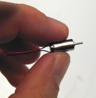
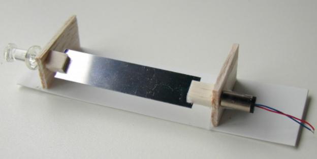
March 15, 2002I made rotating mirror prototype with a small pager motor (Mabuchi J20WA, by Ballooncraft, http://www.toytx.com/6mm13vpagmot.html) (Figure 41).
The sides and the mirror holders are made of balsa wood. The base is made of ABS. The performance is surprising: the motor, driven with 1.5V, spins the mirror, a 1/2 inch x 55mm stainless steel strip, nicely, if the sidewalls are aligned perfectly. And it is amazingly quiet! (Figure 42)
Main problem with this design: the mirror might not be torque resistant enough. [My solution later will be: use two mirrors, and a steel rod in the middle.]
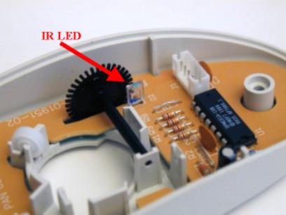
Next I opened four very old computer mice in order to examine their opto-mechanical shaft encoders (Figure 43).
Then I had a meeting with Vadim:
To control a motor backwards/forwards, use a specific chip, e.g., L293D. Two pins of the PIC would control it: the first makes it move in one direction, the second in the other. Do I have two free pins? http://www.alltronics.com/download/1330.pdf
Connect one pin to ENABLE1 and the other to ENABLE2, and then take the voltage from OUTPUT (where exactly?)
PIC with more memory: 16F877 (there are more models coming, but not available yet). Very big, but has more memory, and there is a surface mount version.
For rotating mirrors: I need a shaft encoder plus IR LED, perhaps take it from a mouse. These components are probably already digital, so they can be fed into PIC. http://www.didel.com/microkit/Prix.html http://www.didel.com/microkit/Encoder.html Optical encoders by HP: http://www.micromo.com/images/HEDL_5500_3.PDF Optical encoder by Honeywell: http://content.honeywell.com/sensing/prodinfo/infrared/application/ap_00031.pdf http://content.honeywell.com/sensing/prodinfo/infrared/application/In8eng.pdf Optical encoder by Omron: http://oeiweb.omron.com/oei/PDF/D21SX198199199.pdf Other: http://www.robologic.co.uk/tutadvshaft.htm Small Bluetooth chip: http://www.alps.co.jp/press/new2002/0228-e.htm Recycled angle-sensor: http://www.convict.lu/Jeunes/Recycled.htm Rotary Encoders tutorial: http://www.ubasics.com/adam/electronics/doc/rotryenc.shtml
March 18, 2002Meeting with Vadim: We tried to figure out how the IR LED and the photoreceptor of the Microsoft Trekker mouse are used.
The IR pulses, and the two receptors (probably vertically) pick it up. I don't need the pulsing (which was used for lower power consumption), and just one receptor.
The middle pin of the receptor has +5V, either of the outer pins can be used to connect to the PIC. A 20K resistor has to be connected between the pin/PIC connection and ground.
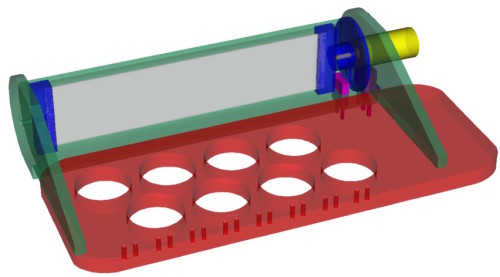
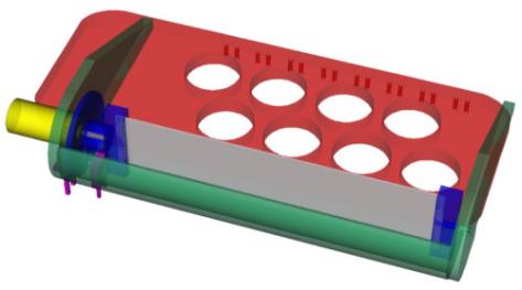
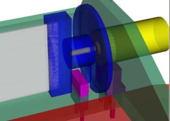
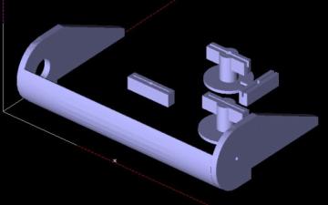
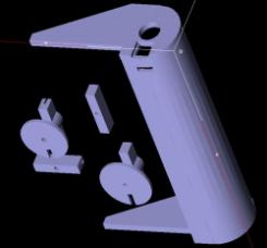
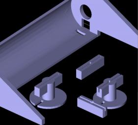
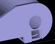
Then I built 3D models of TinyProjector prototype 3 (Figure 44): a rotating two-faced mirror add-on for the second prototype. It uses the before mentioned stainless steel strip (1/4th inch x 55mm).
I also modeled the laser diodes and lenses, all to scale.
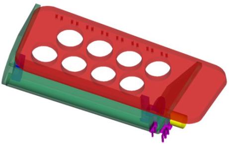
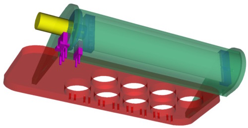
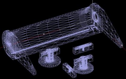
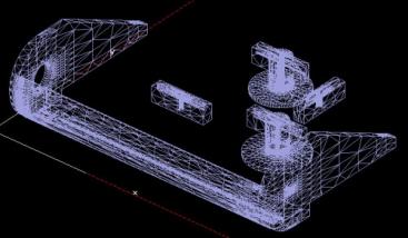
March 21, 2002I installed Rhino2 (which can write STL files), and Quickslice (at home and at the lab, requires higher display resolution than laptop can go). Played around with 3D model of TinyProjector prototype 3 (base, slicing, etc).
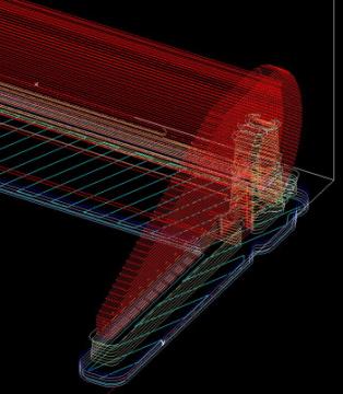
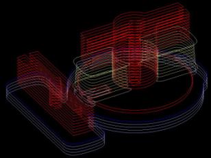
The following screenshots (Figure 45, Figure 46, Figure 47) are from Quickslice, the program that takes the 3D model (e.g., from Rhino, see above), and generates the slices and paths for the 3D printer.
Send me some comments! Copyright © 1997-2004 by Stefan Marti and MIT Media Lab. All rights reserved | ||||||||||||||||||||||||||||||||||||||||||||||||

