Diary of October 2001 1-7
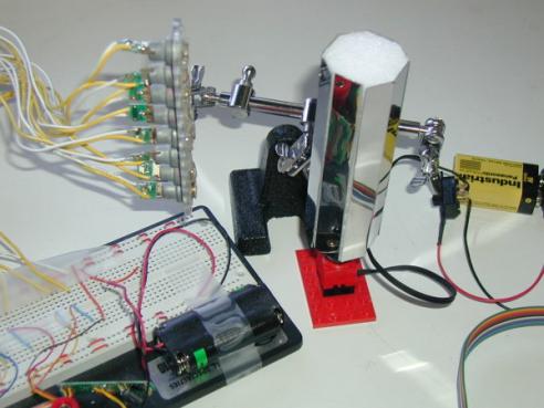
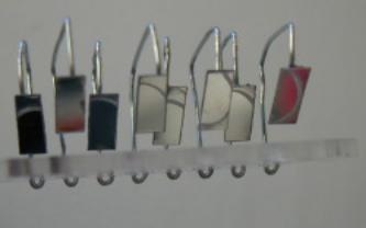
October 2, 2001In order to test the design hypotheses, I am making two 8-sided mirrors, with stainless steel strips (1/2 inch wide), and a Styrofoam core (see Figure 17).
October 3, 2001I tested many glue types (rubber cement, white glue, plastic two component, epoxy two component) to see how to glue the mirrors to the Styrofoam: epoxy resin works best.
I completed the 8-faced rotating mirror pillar, and added a motor (with 9V battery and on/off switch) by Lego. Works much better than by hand, but the projection is still not readable.
Possible reasons for the bad projection:
o The alignment of the laser beams is rather bad. Since the eight laser beams to not form a straight row of dots, a readable projection is impossible. o The speed of the rotating mirror is too fast: the dots become lines. Reducing the pulse time of the lasers can solve this problem. o The refresh rate is still too low. Basically, the brightness of the laser diodes is too low for a projection angle of 90 degrees (which is invariably coupled to the 8-faced mirror).
The above limitations are severe. After having seen the prototype in action, I decide to change the design completely.
The next prototype I will design with a mirror that moves from left to right and back, driven by a servo. The advantage is having a smaller mirror, while still having a full 100% duty cycle of the laser beams.
However, such a construction has the following issues:
o Vibration will occur, since the rotation (angular movement) is not continuous, but changing back and forth. o Closed loop necessary: The lasers beams have to be synced with the position of the mirror since they have to know when to start projecting. o More complex computation: In order to obtain 100% duty cycle, the lasers have to be able to write from left to right, as well as from right to left. o
Sinusoid movement of mirror is bad: It would be easy to have a sinusoid movement
of such an assembly, for example with a crank on a small motor. But a
non-constant speed of the laser sweeps will be difficult to compensate with the
pulse lengths. Therefore, in order to have constant speed of the sweeps, the
mirror has to be driven with a square wave movement. (Basically, the speed of
the mirror has to be constant over the whole projection range, and can’t slow
down at the turning points. But that’s exactly what would happen with a simple
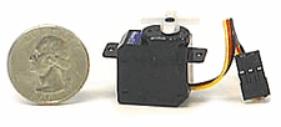
crank on a motor as the actuator.) A simple implementation of such a back-and-forth movement could use a micro servo, like the WES2.4 or the Hitec HS-50 (Figure 19). The servo could be controlled directly by a PWM generated by the PIC chip (which is relatively trivial). The advantage would be that the positioning of the mirror could be controlled very accurately, and as a consequence also the rotation speed.
Furthermore, synchronizing the mirror with the laser pulses is doable, because the PIC chip that generates the pulses also defines the position of the mirror.
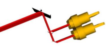
The downside of using a servo is that it is relatively noisy and power hungry (100mA). In addition, the maximum sweep time (left to right, 60 degrees) of these servos is 0.2 sec (WES) and 0.09 sec (Hitec). The sweep time of the mirror however could be increased easily by gearing up the connection between the servo and the mirror, e.g., by using only 30 degrees (or less) of the servo deflection to rotate the mirror 90 degrees. This will work if the forces involved in turning the mirror are very small, which requires a very light going hinge of some kind.
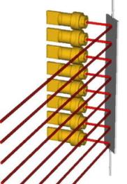
In addition to having a left-right sweeping mirror, the next prototype will have another improvement: it will be much smaller. In the current prototype, the overall length of the assembly is given by the linear array of 8 lasers, which in turn is given by the diameter of the laser diodes.
Since I do not have access to a miniature commercial laser array (e.g., Honeywell), the outer diameter of my laser diodes dictates the minimum length of the array. With a casing that has a diameter of 11 mm, the minimum length will be 88mm. However, the laser beams could have been closer to each other, since the diameter of the beams is only about 3mm.
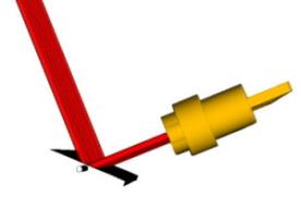
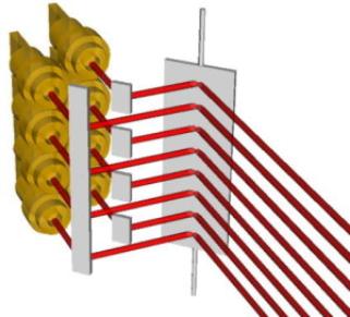
Therefore, in order to reduce the overall width, I intend to build a holder for two rows of four lasers, where the two rows are slightly offset. To align them, small secondary mirrors are necessary. Like that, the two rows of laser beams get directed to the main mirror (left-right sweeping) as a single row (Figure 20, Figure 21).
I need the small secondary mirrors to align the planes of the two rows of lasers. Therefore, I bought many different kinds of tiny mirrors, beads and stainless steel strips, at the Pearl Arts and Crafts store in Cambridge.
I conducted several tests of how to assemble small mirrors, made of stainless steel strips and paperclip wire, for the 90-degree deflection of the two-row laser pointer assembly.
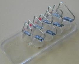
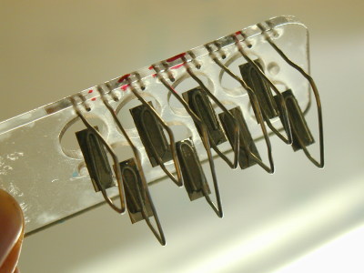
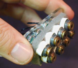
October 4, 2001I worked on the TinyProjector prototype 2: I cut some Acrylic parts on the lasercutter (lower part, containing servo), manufactured eight miniature mirrors, made of stainless steel and paper clips, and glued everything together with epoxy resin (Figure 22).
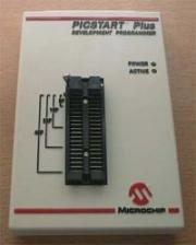
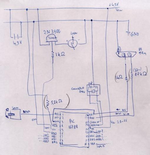
October 5, 2001I borrowed a PIC programmer (Figure 23) from Bakhtiar Mikhak (mikhak@media.mit.edu), and a serial cable that works with it from the Borglab.
I have programmed PICs many times before already: for my Free Flying Micro Platform project, I used several PICs, some for creating the PWM signal to the RC handset, some for reading the two analog signals of the micro compass and creating a heading angle, and then transmitting this angle over the serial wired port, both wired and with a transceiver. But that is already some years ago, so I had to refresh my memory.
PIC programming tutorials:
In order to control a servo, I need to create the right pulse width modulation (PWM) with the PIC. · http://www.inchlab.com/2servo_interface.htm
First try for pseudo code for the PIC controller (no serial input):
Message = (T, H, I, S, _, I, S, _, A, _, T, E, S, T) For all characters of message: set servo PWM to minimum (servo goes to full left position) look up character pattern, blink lasers for 5 time slots each For all characters of message: set servo PWM to max (servo goes to full right position) look up character pattern, blink lasers in reverse for 5 time slots
Code for PIC: with serial input - Read char if char is sync char (0xFF) for 30 characters: read char
October 6, 2001More useful information about writing PIC code:
· http://www.ccsinfo.com/v3.txt · http://www.ccsinfo.com/overview.html
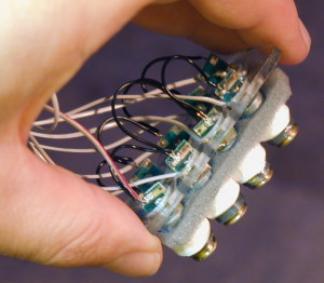
Then I soldered the diodes to the multi-line cord (Figure 24), calibrated the mirrors, and set up the second breadboard.
October 7, 2001I solved code bugs: calibration, length of signals (pulse, spaces between pulses, space between characters, number of characters, servo elevation)
Hardware problem: The servo PWM getting jammed if PIC turns on more than 4 laser pointers. Solution: it needs 1K resistors between the B pins and the transistors. (Many thanks to Matt Reynolds, matt@media.mit.edu!)
Isolation problem: Laser 5 and 7 always were lighting up simultaneously—they couldn’t be controlled independently. After a long time, I found out that this is because the metal shells are connected to the positive tab of the diode, and the two diodes were touching each other. So current to one laser turned on the other, too. I took the whole assembly apart and isolated the shells of the diodes. (Again, many thanks to Matt Reynolds who mentioned this fact to me actually much earlier—I just forgot about it.)
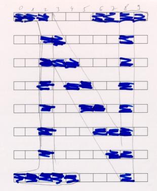
Character set
To create the character fonts, I first thought I would be able to find them on the Web. Here are some related sites about character set fonts (5x8, 5x7):
Eventually, however, I ended up designing my own fonts. I was using a grid printed on a paper, then drew a big character on top of that, and then extracted the dots that are necessary to display the character (Figure 26).
[Note: I didn't sleep that night, went home Monday morning at 9:30am and slept Monday 10am - 2pm.]
Send me some comments! Copyright © 1997-2004 by Stefan Marti and MIT Media Lab. All rights reserved | |||||||||||||||||||||||||||||||||||