Diary of May 2002 1-2
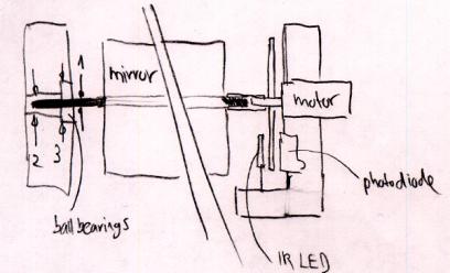
May 1, 2002I drew a sketch of how the rotating mirror assembly (with disk for photodiode/IR LED) might look like (Figure 86).
I tested the rotating mirror assembly with an always-on laser diode: it works, draws a nice thin line on the wall, but the brightness of the Lumex laser diode is very low, probably too low; the same result with a key chain laser pointer.
Thinking more about that, I realized that there is a fundamental problem with having a 360-degrees continuously rotating mirror. If the projection angle is 60 degrees, then the mirror has to rotate only 30 degrees to create this projection. In other words: the laser diode is turned off during 330 degrees of a full rotation, or during 92% of the time! After the projection, the laser has to wait until the mirror rotates for another 330 degrees, and only then can light up during the last 30 degrees in order to create a 60-degrees projection.
This has a very important consequence: Such a low duty cycle requires a very high power laser diode. E.g., a laser diode that can project during 100% of the time creates a 12.5 times brighter projection than a laser diode with a duty cycle of 8% (or dead time of 92%). And this is exactly the problem with patent 6222459, mentioned earlier (see Figure 36). Theoretically, it works, but it is terribly inefficient!
This numbers get a bit better if the mirror has two usable surfaces, e.g., front and back of the same plane. With two surfaces and a projection angle of 60 degrees, the two-sided mirror uses 2x 30 degrees or a full rotation for projection, but is still unusable during 300 degrees of the rotation, or during 83% of the time. Such a projection would be still almost 6 times less bright than a construction that allows the laser diodes to run at a 100% duty cycle.
There are two constructions that allow a 100% duty cycle for a 60-degrees projection:
1. 12 mirrors mounted on the outside of a tube (see also the calculations of Table 1) 2. Single mirror with a left-right sweeping motion
Solution 1 is unacceptable because such a mirror assembly would get very bulky (see Figure 17, a picture of a 8-faced mirror). The reason is that the width of each mirror cannot be reduced beyond the diameter of the laser beam, which is typically around 3mm. Even worse, depending on the angle with which the laser beam hits the mirror, each of the 12 mirrors has to be remarkably wider than the diameter of the laser beam itself.
Solution 2 does not have this disadvantage, since there is only one mirror surface necessary, but it suffers from another disadvantage: vibration. Minimizing the mass of the mirror, however, will minimize vibration.
For all these reasons (and since I do not have access to super bright laser diodes), I continued working on a back-and-forth sweeping mirror construction (see also Figure 81, Figure 82, Figure 83).
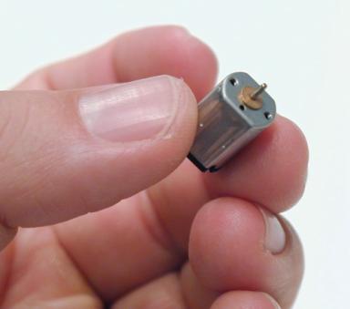
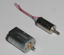
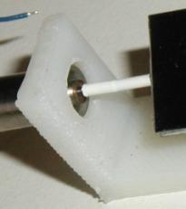
In a first version, TinyProjector prototype 7, I used a 6mm pager motor (Mabuchi J20WA) with a single-arm plastic crank (Styrene) mounted on the axle (Figure 87). Unfortunately, with 1.5V current, the motor was not able to swing the mirror (1/2 inch stainless steel strip) at an acceptable speed. The assembly works with 3V, but gets noisy and, more importantly, the motor gets very hot.
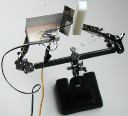
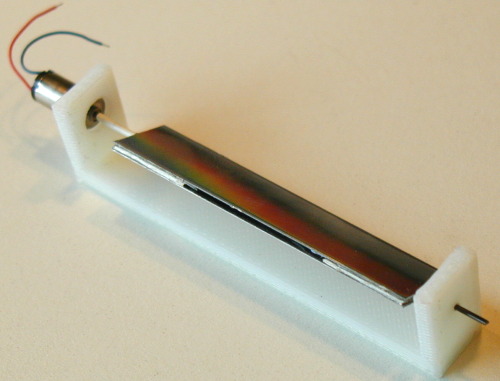
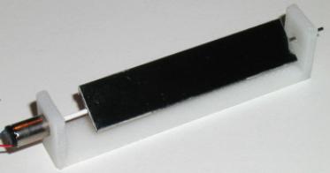
Since the 6mm motor did not seem to be strong enough, I made another sweeping mirror assembly (TinyProjector prototype 8), with the bigger pager motor, a Mabuchi MV2A.
In the Ballooncraft™ where the Mabuchi J20WA comes from, it works with 1.5V (nominal voltage). At this current level, the noise of TinyProjector prototype 8 is acceptable, but the vibrations are rather strong, as expected. Nevertheless, the big advantage is that the laser beam can work with a duty cycle of 100%! Even if I only use one direction of the sweeping movement, the laser is on at least on 50% of the time. The hinges, made of Scotch tape, wear out quickly, though. This is understandable with the high sweep rate. Because the hinges fail gradually, the movement from left to right and the one from right to left do not really overlap. Better hinges will be necessary.
Because of the severe vibration, Eric suggested again looking into the multi-sided mirror option. He suggested using the hexagonal brass tube that I happened to have lying around, but it is not a good enough mirror. The square aluminum tube (1/4 inch) seemed to be another option, so we went downstairs polishing it. The ultimate solution would be a square or hex stainless steel tube/rod that is polished to mirror quality. Eric says that MIT Central Machine could do that for me, and we looked it up in McMaster-Carr (searched for "hex").
I disassembled a key chain laser pointer of the new batch to harvest the 8th mirror that was missing. It was very difficult because the screw that holds the lens is now made of plastic, and cannot easily be unscrewed. I ended up cutting the casing up from the other side (very tricky). I hope this is the only laser pointer of the new batch that is so difficult to open. The mirrors are now fixed with two narrow Scotch tapes, covering about 1mm on each side of the lens.
On the breadboard, I set up the laser diode with the transistor, after consulting with Vadim about if it is OK. He said that the 100-Ohm resistor might be too much because the transistor itself acts as a resistor. First, it didn't work at all, until I realize that the 2N3906 transistor makes the laser light up inverse to the already connected LED! (I had to write a short program that just flashes all C port pins to find that out.) Then I played around with the potentiometer of the laser diode, and I must have damaged the diode: it got worse and worse. Then I tried the third laser diode, and the 100-Ohm resistor was actually exactly the right resistance.
Because I have only 8 Lumex diodes left, I ordered 8 more from Digikey. It would be too bad if I would run out of diodes in the next few days!
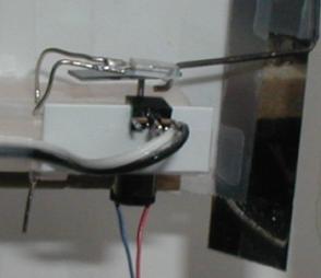
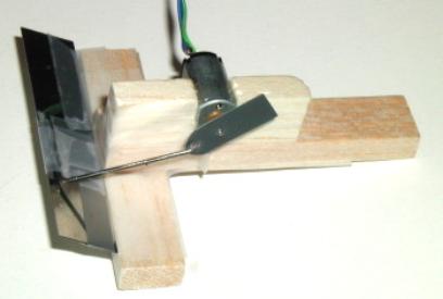
May 2, 2002I added the photodiode to the larger sweeping mirror assembly, to make the system finally closed-loop. The IR light is not necessary; daylight seems to be enough to trigger it. The "servo arm" that holds the pushrod (on one side) and covers the photodiode (on the other, longer side) is made out of black Styrene. (It is thinner than the white ABS, although the packaging says the Styrene strip is 0.8mm thick and the ABS 0.5mm. That must be a mistake.) Perhaps I should use balsa, or thicker and more stable ABS and paint it black (the white ABS does not block the IR light for the diode!)
I wrote some code that starts a blinking sequence when the black plastic part covers the receptor, but it is hard to find out if it does the right thing without actually seeing the laser blink in the mirror. (I just checked with the attached LED.)
I made a presentation for Chris, showing him all current prototypes, and describing the current problems: rotating mirror is best because of low vibration and energy consumption, but bad for light efficiency (laser line only very thin). Sweeping mirror is more efficient but vibrates a lot and is noisy. I will probably follow up on both construction designs.
I talked to Willy a lot: he showed me his optical galvanic scanner (probably an open loop galvanometer). It is heavy and does only a very small angle, but eventually that is probably the right way to go. There will be a trade-off between mirror size (his current mirror is very small), torque, angle, power consumption, etc. Note that the latest version of TinyProjector is actually a closed-loop system!
Galvanic scanners:
Theory of galvanic scanners:
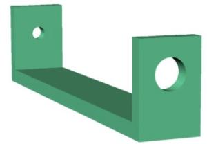
Although I was working on a left-right sweeping mirror assembly (TinyProjector prototype 7 and prototype 8), I kept on working on a continuously rotating mirror assembly. I designed and 3D printed a holder for the rotating mirror, a simple U shaped piece (Figure 92). This is following up on the wooden holder made earlier (Figure 85), which was named TinyProjector prototype 6:
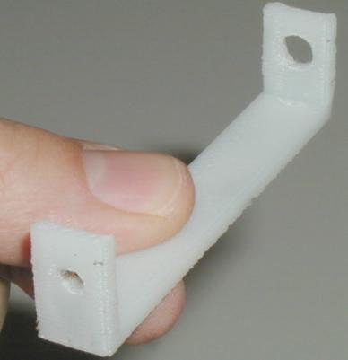
Although the 3D model looks acceptable, the 3D printer had problems with it. The side walls had to be built up vertically, so the holes for the ball bearings (3mm) and motor (6mm) had to be filled with a lot of support material. This is problematic, especially at this small size and with a vertical hole. So neither of the holes came out well, and I had to re-drill both of them manually (Figure 93).
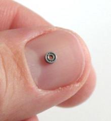
Furthermore, when I tried to insert the ball bearings (Figure 94) into the sidewall, I damaged them, because the hole was not big enough, and I applied too much axial pressure. Obviously, ball bearings of this size and type are rather sensitive to axial pressure.
Interestingly, later I found out that if the whole assembly is hold vertically, the white tube (plastic coating) that connects the motor axle to the mirror axle is rigid enough to make the mirror spin freely, without any support on the other side! I concluded that the ball bearings do not seem to be very crucial in this construction.
So I made a new U piece (U_piece2), with no holes. I drilled the holes afterwards (6mm on the drill machine, the 1mm hole manually), and it works very nicely, even without the micro ball bearings (Figure 95). It looks like the ABS (3D printed plastic) friction properties are close to nylon bushings.
However, for reasons mentioned before, the rotating mirror seems very nice and quiet, but is nevertheless terribly inefficient. This approach turned out to be a dead end.
Therefore, I continued working on the smaller sweeping assembly (see Figure 87 and Figure 88).
After some tweaking, the smaller assembly with the 6mm motor is now working with 1.5V, and is much more quiet and has less vibration than the bigger one. I think I should go with this one. I just have to find the right hinges: they have to be very light going, and still hold longer than normal scotch tape. Perhaps using real hinges? If the hinges are not stable, the mirror wobbles (a so-called cross-axis wobble), and the lines painted by the laser are not straight, but somewhat curved. Of course the stainless steel mirrors are not optimal: probably best would be optical grade beryllium for its superior stiffness-to-weight ratio.
The correct sweeping angle of the mirror seems to be about 35 degrees: measured from the horizontal, the upper position is 80 degrees, the lower position ca. 42 degrees, which results in a 38 degrees sweep (see also Figure 82 and Figure 83). This is based on a servo arm of 4mm, pushrod length of 20mm, and the pushrod is mounted on top of the mirror. (The elevation of the top edge of the mirror is about 9mm). It is smaller than with the bigger sweeping mirror assembly, which has probably about 80 degrees. The smaller the angle, the brighter the laser painted line, the shorter the length of the laser painted line (of course). It is important to find the "sweet spot" between length of line (amount of characters that can displayed) and brightness. In this assembly, the angle of the laser should be about 0 to 10 degrees (measured from the horizontal base line).
Send me some comments! Copyright © 1997-2004 by Stefan Marti and MIT Media Lab. All rights reserved | ||||||||||||||||||||||||||