The applications very much depends on the choice of music synthesizers. Or, the choice of synthesizers depends on the applications. Which one is more important ? It all depends on what you want to do ! This chapter will describe two examples of applications for the Squeezables.
The first application of the Squeezables that came to mind was to shape sound. But how do we want to shape the sound ? One idea is to change its Fourier spectrum or timbre. Since there are many ways of changing the characteristics of a sound, I had to look for a suitable sound synthesis method that allowed me to manipulate its parameters to produce noticeable changes.
With the squeezable cluster, I have six different continuous controls that give me MIDI values from 0 to 127. The Yamaha VL-1 was chosen at the beginning because it has at least eight parameters for each and every sound it models using acoustic modeling. One disadvantage of the controls of the VL-1 is that besides the usual pitch shifting and tremolo effect, the other controls are all too subtle to be perceived, rendering it not a suitable synthesizer to use for sound sculpting.
I also considered the possibility of using the Yamaha SY-77 synthesizer, which is based on Frequency Modulation (FM) [Cho73] synthesis. The controllable parameters are the carrier and modulator frequencies and also the modulation indices. Although FM synthesis can give very noticeable timbre changes, with only FM synthesis available, the sounds generated are very "FM" and noise-like.
In collaboration with Gil Weinberg, the Nord Lead [Cla97] "Virtual Analog" synthesizer was chosen. The Nord Lead is basically a simulated analog synthesizer with MIDI controls to the parameters of its filters and oscillators [Moo65]. FM synthesis can also be done by making the right connections between oscillators. Furthermore, each and every channel of MIDI in the Nord Lead can be assigned different patches to do different sets of analog synthesis, making it possible to generate 16 different sounds with real-time changes of their timbres. All the analog synthesis in the Nord Lead is done digitally making it a very powerful MIDI controllable sound module. It is well suited to our sound sculpting or sound shaping application.
After we chose to use the Nord Lead for the sound sculpting, the next step was to do the mapping. We used a graphical programming environment for MIDI called Max [Opc95].
After experimenting with the parameters and values on the Nord Lead, Gil determined and recommended that the best controls to use are frequency, resonance, FM amount, pitch bend, semi-tone, arpeggio rate, arpeggio range and morph wheel. These parameter names are exactly as labeled on the Nord Lead. The frequency parameter controls the fundamental of the note; resonance sets the frequency of the peak in the filter spectrum; FM amount is the modulation index of the FM generator; pitch bend is the shift in the fundamental frequency; semi-tone is the tuning between the carrier frequency and modulator frequency in FM; the rate of change is the frequency of the LFO (Low Frequency Oscillator) or "the speed of the vibrator;" arpeggio rate is the speed of the built-in arpeggio generator; arpeggio range is the range of notes of the arpeggio generator; and morph wheel is the control to blend or "transfer" between two sounds generated by the Nord Lead or the continuous fade between two sounds. These parameters are interdependent among one another because of the fact that we are only changing the timbre of one note.
I wrote and designed many Max objects that control the various parameters Gil recommended. There is also a limit patch I called FSRXlateTimbre that makes sure values used are not beyond the boundaries defined earlier. This object is used many times in the main Max patch called Nord Lead Timbre Demo. They are tied in between the output values from the digitizer and the controllers for the Nord Lead.
Gil then used the main Max patch to select and tune the parameters for the Sound Sculptor, and we both became the judges for the sounds produced during the active squeeze test sessions.

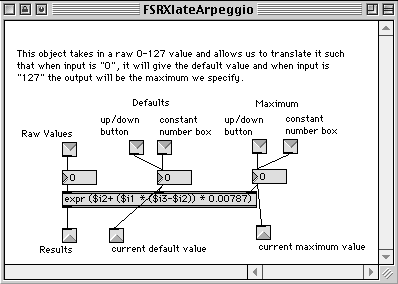
This Max patch takes in three values. The first value it takes in, "Raw Values" or $i1, has a range from 0 to 127. It is then scaled to be between the "Default" or $i2 and "Maximum" or $i3. This is done by dividing $i1 by 127, which is the same as multiplying by 0.007874. This result is then multiplied by the difference of the "Maximum" and "Default" which is then added to the "Default". This yields the effective range of numbers with the new boundaries.
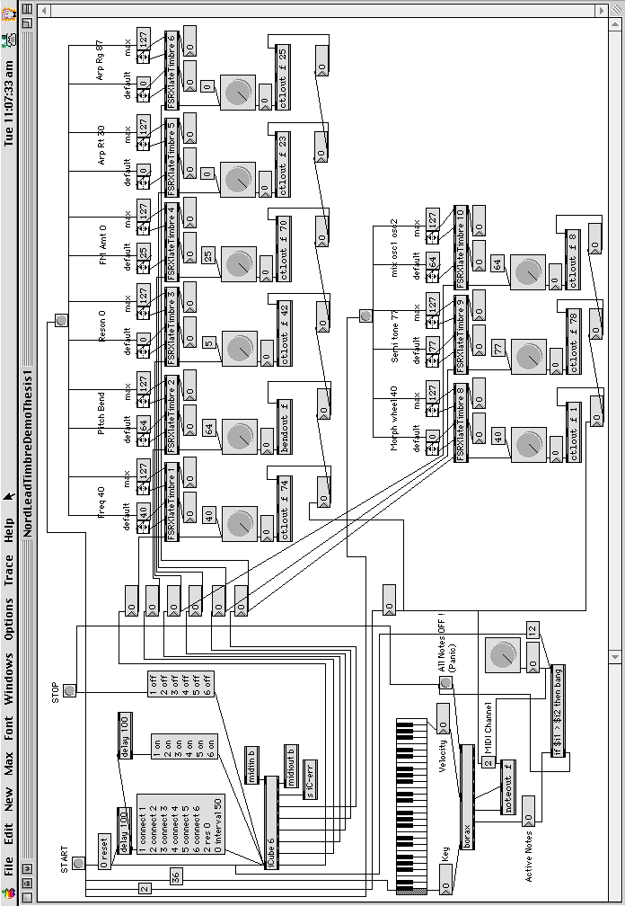
This is the main Max patch which controls everything in the sound sculptor (Fig. 6.2).
In this patch, there are the START and STOP buttons which start and stop the I-Cube digitizer and also the Nord Lead synthesizer. When the START button is pressed, the I-Cube digitizer will start the A/D conversion of the specified channels and we will see the values in the various number boxes change as we squeeze the cluster. These numbers are passed through to the various FSRXlateTimbre sub patches that will scale the incoming values into the a range of values between the "default" and the "maximum." For example, for the "FSRXlateTimbre 1" sub patch for "Freq," the minimum and maximum values the patch will produce are 40 and 127 respectively.
The controller numbers for frequency, resonance, FM amount, arpeggio rate, arpeggio range, morph wheel, semi tone and mix of oscillators 1 and 2 are 74, 42, 70, 23, 25, 1, 78 and 8 respectively. The pitch bend is done through the "bendout" object. The graphical dials and number boxes appearing after each FSRXlate sub patch are used for debugging and monitoring purposes.
When the START button is triggered, a MIDI note number 36 will be switched on at the Nord Lead synthesizer. Until the STOP button is triggered, the note will be held as long as we need it. The note held will be shown on a little keyboard and then passed into the "borax" object and into the synthesizer. The number 2 box appearing after the START button on the left gets sent to all objects that need to know the MIDI channel where everything is supposed to happen. In this case, it is MIDI channel 2. The "borax" object is used to make sure that whatever notes we switch on will be switched off completely when we trigger the "All Notes OFF" button on its right. This will ensure that there will not be any stuck MIDI notes when we stop the main patch.
![]()
In order to create this application, I took some basic lessons from Gil Weinberg about the various functions and components of an arpeggio. It consists of a few basic inputs : base note, register, interval, accent, note hold duration and of course the tempo. There are also different ways to play the notes generated. One example is to play from the base note and up, down, up and so on. Other ways may be to always start from the base note and up and from the base note again; from the base note and down, up, down and so on; always down from the base note etc.
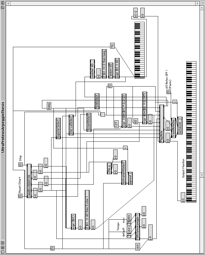
I wanted to create an arpeggio generator that could do all these variations but decided to create one that starts playing from the base note and up, down, up and so on. The reason for doing this is to simplify the programming tasks in Max. With this information, I created a main Max patch called "UltraProteusArpeggio" (Fig. 6.3) that handles all the parameter changes for the arpeggio engine called "PlayNote" (Fig. 6.4).
In the "UltraProteusArpeggio" main patch, there are the "InstrumentSelect", "RegisterSelect", "IntervalSelect", "AccentSelect", "HoldSelect", "TrackNoteOns", "FSRXlateArpeggio" and "CubeBox06b0106" sub patches. All these sub patches are created to hide away the detailed functions described by their names so that the main patch is more easily understood and presentable. The long keyboard at the bottom of the patch is used as a monitor for the generated notes whereas the shorter keyboard on the right is used to monitor the base note selected for the arpeggio engine.
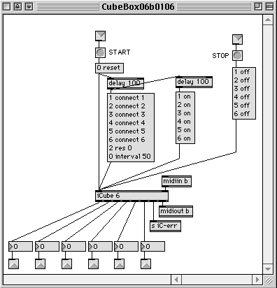
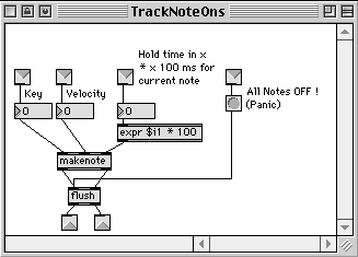
The "CubeBox06b0106" (Fig. 6.5) sub patch has all the controls, sampling rate, channel assignments and resolutions for the ICube digitizer. The "FSRXlateArpeggio" (Fig. 6.6) is basically the same as the "FSRXlate" (Fig. 6.1) that scales the input to a defined and bounded range. "TrackNoteOns" (Fig. 6.7), which utilizes the "flush" object that keeps track of all the note ons, is used at the output end of the "PlayNote" to ensure that there will not be any stuck MIDI notes after they are done playing.

![]()
The "PlayNote" sub patch, which is essentially the arpeggio engine itself, takes in a total of 10 parameters for an arpeggio to be generated. The first one is the "Reference" or base note, which is taken from a random number generator generating a number between 40 and 100. This note can also be assigned by the user at any time. A counter keeps count of the time length this note will be used before changing to a new note.
The "Register," consists of a pair of numbers, i.e. the lowest and highest MIDI note numbers relative to the base MIDI note to play and is used to make sure the notes generated for any arpeggio does not go beyond these boundaries. When the next calculated note is higher or lower than the preset boundaries, it gets wrapped around at the boundaries, changing the direction of the arpeggio from up to down or vice versa. Values for this input come from the sub patch "RegisterSelect" (Fig. 6.8) which divide up the 0-127 sensor values into 7 segments. When the sensor input falls within the first segment, "0 0" will be used. The next values will be "7 5", "12 12", "19 17", "24 24", "31 29" and "36 36."
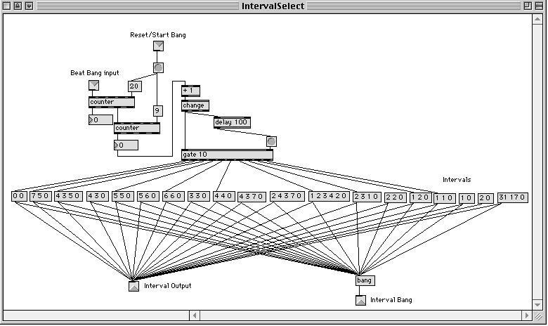
The "Interval" is a list of numbers, up to a maximum of 5, ended by a "0" or zero value. These numbers are used in a loop form to calculate the next note to be played. For example, a list of "7 5 0" will result in note 7 semi-tones away from the base note with the next one at 5 semi-tones away from the second note. The whole process repeats itself by adding 7 and then adding 5. If it is a downward arpeggio, 5 will be used to subtract from the base note and then 7 will be used to subtract from the next note. The "Interval" input takes values from the sub patch "IntervalSelect" (Fig. 6.9). This sub patch loops the 10 predefined interval values "0", "7 5", "4 3 5", "5 5", "6 6", "4 4", "1 2 3 4 2", "2 3 1", "1 2" and "1 1".
The "Accent" is also a list of numbers, up to a maximum of 5, also ended by a "0" or zero value. These numbers are also used in a loop form to put emphasis on notes generated. Together with the next two inputs "Accented Velocity" and "Non-Accented Velocity", this part of the patch will generate a velocity for the computed note. For example, the list "3 2 2 0" will emphasize the 3rd note, the 2nd note after that and then the 2nd note after that one. This will repeat starting with 3. The inputs come from the sub patch "AccentSelect" (Fig. 5.10) which splits the 0-127 sensor input into 10 segments covering "8", "4", "5, "2", "4 3", "3 3 2", "3 2 2 1", "2 2 3", "1 1 2" and "1".
The next three inputs "Tempo", "toggle on/off" and "Reset" determine the speed of the chord progression, whether to start or stop the generation of the note and to set the arpeggio engine to the beginning (starting at the base note) respectively. Since the tempo object in Max is not able to generate very fast clock ticks for the arpeggio generator, this "Tempo" value is different from the normal beats per second. It takes values from 0 to 260 and will generate a value from 600 to 1 and is used as a timing number in milliseconds for the "metro" or metronome object in Max.
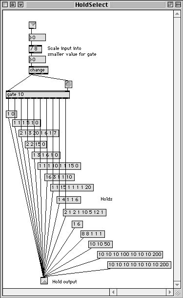
The last input of "PlayNote" is the "Held Note List". This takes an input of a list, up to a maximum of 8 numbers, that tells the engine the hold time of a generated note. For example, a list of "2 2 15 0" will hold the first and second notes for 200 milliseconds, the third note for 1.5 seconds and not hold the fourth note at all. The data comes from the sub patch "HoldSelect" (Fig. 6.11) which segments the incoming 0-127 sensor values into 10 parts. The 10 sets of values are "1 0", "1 1 1 5 1 0", "2 1 3 20 1 6 1 7", "2 2 15 0", "1 3 1 16 1 0", "1 1 1 10 1 1 15 0", "16 3 1 1 10", "1 1 15 1 1 1 1 20", "1 4 1 1 6" and " "2 1 2 1 10 5 12 1".
The only sub patch that is not used by "PlayNote" is "InstrumentSelect" (Fig. 6.12). The patch also splits the 0-127 sensor values into 10 segments covering 10 sets of numbers "0", "16", 106", "48", "9", 96", "62", "5", "13" and "100". These are instrument numbers in the E-Mu Ultra Proteus synthesizer. One difference this sub patch has when compared with the others is the ability to switch to a fixed number, 15, when it detects a press in the foot pedal. When the foot pedal is tapped once, the arpeggio engine will play only percussive sounds from the synthesizer. When the pedal is tapped another time, one of the 10 numbers will be selected again and the arpeggio will drop out of percussion mode back into other musical instruments. The "Reset" in the "InstrumentSelect" sub patch will set the arpeggio engine to play the grand piano sound from the synthesizer.
In this application, the E-Mu Ultra Proteus synthesizer is a good choice because with this instrument, notes do not get cut off during instrument change.

