After the testing of the squeezable foam ball cluster, several observations led to the development of the pole of squeezables. Here, the design and construction of the pole station is described.
The most important lesson learned from the squeezable foam ball cluster is the desirability of "group play." The cluster cannot be played by more than one person at a time, causing people to queue up to wait for their turn to play with the Squeezable.
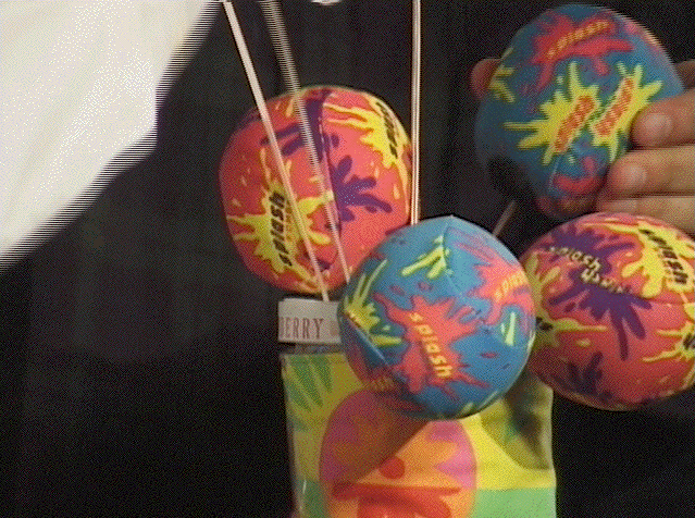
The next version of the Squeezable, called the Pole of Squeezables, has all the little squeezable balls on top of a pole as a group but they can be separated. Each and every ball can be squeezed independently. This way, the cluster configuration is still preserved and at the same time, it is possible to reshape the cluster into many different shapes. With the cluster that can be separated, a group of people can play the Squeezable together and not have to wait in line.
Since the cluster is now on top of the pole and the balls separable, it makes sense to let people pull the individual balls from the pole or station. The elastic bands that hold the balls together pull them back when they are released from pulling.
To prevent the foam balls from tearing and flaking off, they were wrapped in cloth. This layer of colorful and decorative cloth not only protects the foam, it also gives the balls a much nicer feel when touched.
The height of the pole was made to be about 117 cm or 3 feet 10 inches from the floor so that users could just walk up to the pole and place their hands on the Squeezables. The outer diameter of the pole was 8 cm and it was made of thick (about 3 mm) cardboard material.
In order to detect the pressures applied on each and every ball, all of them needed to have pressure sensors embedded. The first idea that came along was to use a little balloon filled with air (a bulb) that attached to an air pressure sensor and was buried in the ball.
However, the bulb will always have some amount of pressure when it is inside of the foam ball because it needs to be positioned at the center. Furthermore, air pressure sensors are precision sensors that are very sensitive to the slightest change in pressure and will always need to be recalibrated for "no squeezing." This is a disadvantage because I wanted the sensors to have a zero value or some constant value when the balls are not squeezed.
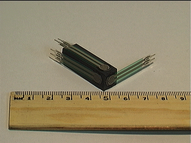
This led me to make a "sensor block" which consists of five 8mm FSRs (Fig. 2.4) at one end of the block (Fig. 3.1).

The five FSRs at the tip simulate the shape of the air bulb and the length of the block serves as protection for the sensor's body and connection. This sensor block is then embedded into the cloth-protected foam ball with the top of the block in the center of the ball. The FSRs are connected in parallel to one another electrically so that they all act like one pressure sensor.
Since the FSRs are less sensitive when compared with the air pressure sensors, they will not require calibration and will give zero values when there is no squeezing. Another advantage is that since it does not use air, there is no air leakage problem to take care of, making it virtually maintenance-free.
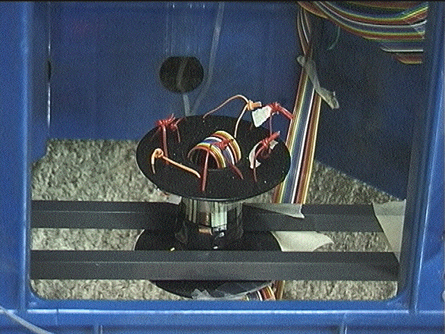
To sense the pulling of the balls from the top of the pole, the original idea was to use a strain gauge. This was too expensive so I came up with the idea of using the 18mm FSRs in a reverse direction. By placing an FSR on a flat surface with some holes around the FSR and a short wire loop, the pulling can be sensed by attaching the elastic band from the ball to the back of the loop (Fig. 3.2). The pull on the loop from the back will push the FSR in front.
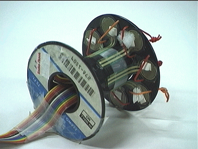
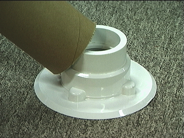
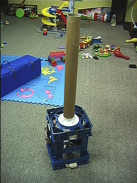
This pull sensor assembly is installed at the base of the tube in a frame. The top of the frame holds the tube steadily through a PVC closet flange (Fig. 3.3) which is screwed down tight onto the frame.
The wires of the balls are then tied at mid-way down the tube with elastic bands to the pull sensors below. When the balls are not pulled from the top of the pole, the elastic bands are not stretched. When they get stretched from pulling, this will pull the wire loop, applying pressure to the FSRs.
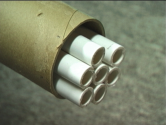
To prevent the wires and elastic bands from tangling up inside the pole, the inside of the pole is partitioned using 7 smaller plastic tubes bundled together forming a "machine gun" (Fig. 3.4). The size of these smaller tubes is about 2 cm in diameter.
When the whole tube assembly is put together with the base frame, it will stand by itself on the floor (Fig. 3.5). The pull sensor is installed at the base of the frame (Fig. 3.6) by two pieces of nylon blocks with the wire loops facing up. With the squeezable balls on top of the pole, the elastics from the wires are then tied to the wire loops of the pull sensor in a way that they are just released. The Pole of Squeezables is then decorated by a piece of cloth wrapped around its body and the players will stand around the pole to squeeze and pull (Figs. 3.7 and 3.8).
The FSRs in the balls and those in the pull sensor assembly are connected to potential bridges (Fig. 2.14) with a 5-Volt power supply and are governed by Eq. 2.1. The output from the bridges are connected the different channels of the I-Cube digitizer (Figs. 2.12 and 2.13) as in the squeezable cluster in Chapter 2. There are fourteen channels of analog signal all together, seven from the squeezing and another seven from the pulling.
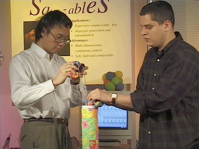
To test the Pole of Squeezables out with people, I asked fellow students, faculty and staff members from the lab to come by and play with it. Many people just walked up and started squeezing and pulling the balls naturally.
However, when children played it, it became clear that the pole was actually too high for them. They had to stretch their arms up to reach the Squeezables and could only pull them to the sides, not up. Pulling the balls to the sides instead of pulling them up damaged the wires after a while. Another observation about the sideway pulling is that the pole started to become unstable because the base was not heavy enough the counteract the horizontal pulling force. To prevent this, I had children or shorter people stand on a raised platform next to the pole and I also added some weight to the base to stabilize the pole. Even with this inconvenience, the children liked the Pole of Squeezables and said it was a different kind of music playing experience than they had ever had. They could stand around, watch one another and also dance with the music/sound generated.
Another issue that came up from user testing is the softness of the foam balls. Many people find that the foam balls are too soft when compared to a cluster of foam balls. This softness of the balls also meant that the users have to squeeze a long distance, almost like collapsing the ball, before their squeezing can be measured by the sensor block.
There were some comments saying that the pole looked strange and "phallic" from a distance because of its shape, color and height.
For the elastics that pull the balls back to the top of the pole, since I used rubber bands, they deteriorate after a while and have to be changed regularly.
Here is a summary of the lessons learned :
2. pole is not stable
3. wires get damaged from side pulling
4. rubber bands break easily
5. foam balls too soft for individual squeezing